Monday, January 29, 2018

Determination of Material Losses

The results of a test to ascertain the dimensional increase in cut length above the nominal value set in software are discussed below.

An increase in power to 20% was required to get a cut through, even after adding more weights to keep the board flat and changing the laser frequency to 125 kHz.  This was not expected because just two days ago with the same piece of wood on the same laser with the same cut speed I was able to cut through with only 15% power.  This tells me that when you're on the threshold of not being able to cut through because you want to  minimize the laser power, the conditions are very sensitive to differences in grain pattern,  density and even possibly the level of the warping or unevenness of the board (even if you are just moving  9 inches down the board).


The inside edges of the frames were all wiped down with a terry cotton cloth to make a clean surface before inserting the cast Plexiglas standardized block.

Tests with inserting a 1.40 inch by 1.15 inch cast Plexiglass plain block reveal that about 0.02 to 0.03 of an inch is lost due to char and burn debris. This is for the horizontal (X) axis direction of the laser chamber coordinate system.

The losses in the vertical (Y) direction are somewhere between 0.01 and 0.02 inches.

While 20% power  may not have been the minimum required to cut through the 3/16th inch wood, it was pretty close and was certainly not overpowering because inspection of the back side of the board revealed almost no burn spots on the nearby sections of board perpendicular to the edges of the cut.

My plan is to cut out a series of five blocks for each of the X and Y directions, this time changing the third decimal place in inches for the length of the cut.

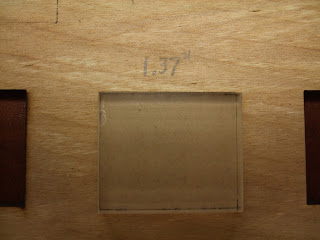
You can see from the picture that the 10 blocks at a first glance all look to have the same dimensions, and yet the lengths are decreasing by 0.01 inches going from left to right as marked numerically in the photograph.  Several zoomed in pictures show how the block falls through cleanly in several of the larger blocks on the left side, but only partially fall through or sit unevenly in a block which is too small to accommodate it.  It was in this manner that I was able to narrow down to a range of losses of material due to the burn and char debris.

Left mouse click on any image to enlarge it in a new window


Note there is some wiggle room around this inserted block


this one a bit less


this does not truly insert


side view


Now the vertical (shorter in this case) length is varied


decreasing to 1.13 inches prevents a true insertion


at 1.12 inches it is obviously not going to insert at all


Wednesday, January 24, 2018

Precision Cutting


Today I started a series of tests to see if a quantitative relationship could be developed to understand how a nominal dimension cut size in software translates into actual dimensions in flat wood. In other words, how much material is lost due to burn and charred dust that makes the cut dimension LONGER than the size indicated in the software design. I found that for a 1 inch block, the gap inbetween the cut-out block and the frame cut around it is about 1/32 inch. Knowing that the laser cut performance varies in the vertical and horizontal directions, I designed a series of 5 blocks for each dimension. The dimension being varied changes by 0.01 inch incrementally (1.39 , 1.38, 1.37, 1.36, 1.35 inches) for a nominal 1.4 inch horizontal. The verticals are varied also by 0.01 inches starting at 1.14 inch to 1.10 inch for a nominal 1.15 inch design dimension.

First, I tested various combinations of power and speed to see whether (a) the cut makes it through wood 3/16 inch thick, and (2) how much char burn dust is created along the cut edges.

This is a Boss Laser LS-2436 150 Watts and 4 inch focal length.

#1 35% power and 25mm/sec speed cut
#2 30% and 25 mm/sec no cut
#3 25% and 25 mm/sec no cut
#4 20% and 15 mm/sec cut
#5 15% and 15 mm/sec cut
#6 12% and 15 mm/sec no cut
#7 12% and 10 mm/sec no cut
#8 12% and 5  mm/sec cut

I assessed which combination of speed and power processes cuts with the least char debris by visually inspecting the sides and wiping all four edges of each cut-out block against the cotton terry cloth pictured below.

Wiping char dust on cloth to find the cleanest cut


To my eyes the 15 mm/sec and 15% power produced the best results.

So, when I set my parameters to 15/15 and ran my series of 10 test blocks, I was surprised to see that none of them had full cut-throughs! As you can see from the photos though, burn lines are evident to different extents on the backside of the wood, suggesting that the power only needs to be increased a bit to achieve full cut-throughs.


Front and back sides of a series of unsuccessful cut-throughs on 3/16 inch wood


Front


Back


What could possibly explain this? Two things that I can think of:

1. There is warping/unevenness in the wood and the metal bricks holding the wood in place are successful to different extents in keeping the wood perfectly flat.  Differences in flatness will affect the ability of the auto focus to work properly and thus affect the cutting strength. I will try to use more bricks to keep the wood flatter.

2. I made a mistake and did not match the laser frequency in the g-code files between the single (125 kHz) and multi-block designs (20 kHz). So I went back and resaved the multiblock deign with a 125 kHz setting and will cut the test series again.

To be continued ...

Monday, January 22, 2018

Cleaning the Plexiglass

I found that using a standard normal size wooden toothpick is a very good way to remove caked on plume haze off the plexiglass. You need to swap out toothpicks frequently, but you get very close to the artwork in tight spaces without ruining it. I also used wire clippers to cut fresh tips on the toothpicks and that can extend the toothpick if you are in short supply. Look at my before/after pictures attached. This was for the single scan of the rosebud.


Before using a toothpick


After cleaning for about 5 minutes with a toothpick


Wednesday, January 17, 2018

Yesterday I used the 4 inch focal length laser to scan a small inch square rosebud image. The image was cropped out of a larger botanical drawing by my mother using colored pencils.


Grayscale modified rosebud


single and triple scanned rosebuds in cast plexiglass


edge view of the single scanned rosebud


edge view of the triple scanned rosebud - a deeper etch.


Number of scans

One etch was scanned once and another one was scanned 3 times. The difference in depth is quite noticeable, as the 3 times etched design is much more three dimensional, although it was also harder to clean debris from it. Debris was cleaned by compressed canned air while the material was in the chamber and by a wet stiff toothbrush in a sink afterwards. I observed that compressed canned air was more effective at loosening and blowing away debris from the crevices of a 3 by 5 inch etch from last week than yesteray's 1 inch square etch.

Bed positioning

I experimented with mounting the cast plexiglass both towards the center, and also on the far right edge of the support bed, to the right of the ventilation holes. I found that considerably less plume debris was deposited on the untreated plexiglass surfaces if the material was more towards the center. I also observed that cut throughs induced orange flames were much longer when the material was to the right of the ventilation holes. I failed to take photos of the flame, and central bed position. The flames were often as long as my index finger without proper ventilation. The pictures will show you the differences on the plume debris deposited on the surface areas.

Plexiglass positioned away from reach of ventilation holes underneath the support bed


Laser head range

The farthest that the laser head can move back is slightly off the edge of the bed so that the positioning red light is no longer visible.  Whether it's acceptable to run the head to its extreme position can be discussed in the lab with co-workers.  It also appears that if you have the laser head moved into position far away from the previous origin, pressing the red ESC (escape) on the laser control pad appears to bring the laser and back to the previous working origin and halts there, but without actually running the file. This behavior of the escape key is not documented in the Operator's manual.

Laser head in resting position


Changing speed/power on the fly

If all you want to do is change the scan speed and power setting of a g-code file already loaded into memory, you do not need to return to your computer and regenerate that g-code file. On the main control screen of the laser, press Enter twice. Then presss the Z/U key to move up and down the editable speed and power fields. Once one is chosen as highlighted in blue, press the left arrow key to underline the numerical value you want to change. Then press the up and down keys of the laser keypad to cycle through the numbers zero to 9. After editing any field, press enter to save it. Press Enter again when done to return to the main menu. A feature of the on-board software is that after editing those parameters, the image on the view screen of your object goes blank. Fix this by pressing the File keypad button, reselect your g-code file from the list, press enter again, and the image thumbnail is again viewable. NOTE THAT THE NEW PARAMETERS ARE STILL IN PLACE; YOU HAVE NOT RELOADED THE ORIGINAL FILE. You simply have woken up the image to become viewable again.

direction matters

When cutting through the plexiglass to get the actual art piece to drop out loose, I noticed that the smoothness and minimization of ridges was far better in the horizontal direction than the vertical direction. I guessed incorrectly that increasing the speed from 15 to 30 mm/sec might improve the overall smoothness of the edges at 70% power. However, doing so failed to cut through the 3/8 inch plexiglass. Since I did not want to increase power further, I reverted back to 15 mm/sec to get a proper cut-through and will accept the smoothness quality as is for now.

Chamber coordinate system

While the scan is running, I observed the X coordinate, Y coordinate and Z coordinate values flashing quickly on the viewscreen. X values increase left to right. Y values increase top to bottom. Z values are steady of course, as neither the bed nor the laser head moves vertically while firing. The Z values were always positive. I therefore surmise that the Cartesian coordinate system of the laser chamber is left-handed.

time efficiency

The software controlling the horizontal gimble of the laser head has been well engineered from a time usage point of view. The X coordinates routinely adjusted based on the number of times the laser would need to fire to etch. In a horizontal row where very few pixels need to be etched the laser head skipped moving through the blank areas left and right of the etchable pixels, saving time.

Laser etching the rosebud into the plexiglass

low powers

You can edit power levels down to as low as 0.1% on-board the laser, but numbers 0.9% or lower are rounded up to 1.0%. A large number such as 70%, if edited to for example, 70.4%, will be respected as such in the main menu. Setting values to 1% is good trick to get a layer to go unfired, instead of needing to create and load a new file from scratch. This only makes sense though if the layer has a short run time.

Saturday, January 13, 2018

I cut a rosebud from my Mother's Christmas Day Rose drawing in Gimp, converted it to gray scale, and rescaled it down to be 1 1/8 by 1 3/8 inches. The exported png file was loaded into RDWorks. Several cycles of previewing in RDWorks and erasing in Gimp were performed to check for and further clean up random backgrounds specks and blemishes. A cut framing rectangle (slightly larger than the rosebud object) was added and both objects were snapped to the upper right corner before exporting to a g-code .rd file for the laser. Before exporting to rd, remember to select both objects.

parameters are rosebud: scan 250 mm/sec, laser freq 10 kHz, 0.035 interval and power min 11/max 25%

Frame box: cut 15 mm/sec min 50/max 50% power laser freq 125 kHz.

The rd file is only 2 Mb and simulation indicates a run time of under a minute.

Friday, January 12, 2018

I am a Scientist using my technical and software skills and experience to explore creative ways to use carbon dioxide gas lasers to cut and etch a variety of materials to produce artwork.

The makerspace laboratory facility I belong to that maintains an pair of Boss Laser LS-2436 CO2 lasers is Build, RVA.

This blog will serve the following purposes:

1. Display photos and videos of both the laser in action and the finished products.
2. Document my progress in the Makerspace Lab.
3. Provide lessons learned and relevant resources for the software required to produce designs that the laser can cut or etch.
4. Provide lessons learned and relevant resources for running the lasers.
5. List and comment on the similar work of other artists.