Saturday, October 20, 2018

First VCarve Pro design

Last night I finished drawing my newest SymArt after cutting the stencil with the 4 inch focal length laser earlier in the week. VCarve Pro is proving to be a faster and more versatile tool for creating artistic geometries compared to Inkscape. Additionally, the Makerspace license is free to install as long as we do all exporting on one of the Build RVA Makerspace desktops (as enforced by the Vectric license). Finally, VCarve Pro is a more reliable exporter of DXF formats for the RDWorks laser preprocessing software.


Notice the blue Painter's masking tape remaining on the stylized tree cutouts. The Painter's tape prevents charring and cracking of the plexiglass at the laser cut edges (especially around the supporting bed blades).

Monday, September 17, 2018

VCarve Pro

Upon a strong recommendation by Seth in early July, I decided to transition away from Inkscape and towards a more advanced and powerful software package called VCarve Pro. VCarve Pro is an all -purpose CNC Routing 2D and 3D job creation package that can also export as DXF, which is perfect for RDWorks. Moreover, Seth is claiming that the DXF export/import process has higher fidelity with VCarve Pro then with Inkscape.

So today I finished reading and practicing through all of the reference manual chapters on 2D job creation and general main menu and right click menu usage.

Seth is correct; the complexity of the stencil designs I can create in a relatively convenient fashion far exceeds what can be easily accomplished in Inkscape.

I am now creating a new main menu tab on this blogsite named VCarve Pro that will contain tips, workarounds and alerts to any usage issues with VCarve Pro.

Save time on color assignments: If you are planning to export your design as DXF for importing into RDWorks, use the layer drop down menu in VCarve Pro to set customized colors for each layer. Put each object (or grouping of similar objects) into a layer by itself. The DXF format will respect that, and so will RDworks when you open the DXF of your design there. Conveniently, all of your color designations and layers will automatically populate into the Work Tab. Then all you have to do is set layer properties of speed/rep rate/power/priority. You are saved the time of assigning colors.

Warning: Sometimes, without any notice, VCarve Pro will save redundant and exactly superimposed shapes upon DXF export.  This has happened to me with VCarve ellipses in particular. This will make color assignments, as mentioned above, not be respected visually on the RDWorks Canvas. Typically, all such shapes will appear as black. If you suspect this is happening, just go to the Layers Work Tab, set the Hide property to "yes" and see if any other exact shape/object is underneath with the color expected. Then just delete the redundant shape/object.

F9 will center a selected object to the material space. You can also use the Align transform tool for this. Don't F9 a group, unless the group is already centered or in the orientation you want. For Groups, F9 will center the central point of the group - not the same thing.

Weld and Intersect: You can't do it to members of a group against each other; VCarve Pro considers the group to be one object. First ungroup, apply the transform with left click selects, then regroup.


Sunday, June 24, 2018

Pushing the Limits on Plexiglass Cutting

Once again I used Inkscape to design a symmetric stencil, this time using spirals and mirror reflecting the copy of the spiral while superimposing it. I then used a line tool to connect the very short (< 0.03 in.) disconnects as the spirals are very hard to exactly superimpose. This is a big test for the laser, as it will have to precisely cross over cuts already made to get the interior objects of the spiral to fall out. How cleanly can it leave very thin and sharp corners and will the shapes fall cleanly out?

I used painter's tape on the back of the plexiglass to reduce cleaning time for debris, cracks and char marks.

The photos show that the crescent shapes are intact even at the thin tips. All interior spiral shapes fell through cleanly except for one which pivoted upwards. The laser had to be stopped or else it could collide with the protruding plastic. The laser does have some issues picking up smoothly after a pause command to the gantry, leaving some rough edges. Next time I will not use any center support bars and this should fix the problem.

The laser power is so strong after a full cleaning of mirrors and lenses that next time I will be looking to drop the power down from 30%. The full run time for the job is less than 6 minutes.


The original Inkscape design


The painter's tape protects the edges of stencil cutouts 
and the outer circle.


All of the cutouts, in good condition.
Click to enlargen.


Monday, June 18, 2018

Change of supplies

After a discussion with Taylor, there has been a change in lens and mirror cleaning supplies. Those of you read my item number 2. in my May 19th post should note that the language has been replaced by:

"We now, under Taylor's guidance, are using a specially formulated lens cleaning liquid in a dispenser bottle that comes with it. Also, we are no longer using the one-time disposal Fluent brand wipes to clean lenses or mirrors, nor are we using any type of rubbing alcohol."

Monday, May 28, 2018

Complex Stencil Cutting

The most recent effort with the laser involved several changes to the procedure:

1. Many support blades were removed to decrease the amount of debris that needed cleaning after the cutting. Fewer support blades also mean that the underside of the plexiglass was LESS likely to chip. The trade off is that there may a bit more bounce when doing the auto-focus, though if starting at a corner this is not so big a consideration. There is also the extra time involved with removing and replacing support blades.

2. I am now using 3 standardized cuts: inner, middle and outer circles. This will allow me to interchange sections of one stencil with a different one to multiply the number of design combinations.

3. The whole deal is getting ready for Hollywood! Not really, but I did capture video and post processed to reduce background and added in photos to tell a nice story. I used Audacity to clean up the noise in the audio track and Movie Maker and YTD Downloader to produce slideshow videos and convert movies to AVI.


I did have one element that was too close to the outer circle cut that soon cracked off after handling. Next time I will be more careful to stay farther from the edge and use masking tape on the backside to hold marginal pieces in place. I still have the inner shape intact so the stencil is still quite usable.

Stencil before and after cleaning with rubbing alcohol
click on the links, then click again on the photos to zoom 
or the video thumbnail to play

Photo link: Before cleaning

Photo link: After Cleaning


Video to introduce the laser cutting process


Video: The stencil actually getting cut


Saturday, May 19, 2018

Aligning the Laser Beam


Monday, Thursday and a long day on Friday were devoted to aligning the beam on the 4 inch focal length laser on mirror #2 and #3. This is a time consuming and careful process that involves a number of minor, sometimes counteracting, adjustments working in tight spaces. In the end the beam was very well aligned and several lab mates were satisfied with the quality of their jobs after the alignment.

Here are the lessons learned:

1. Don't rely on the red beam.


To save time on frequently closing the side doors and lid for every laser test pulse, as well as being able to see the beam, I decided on Thursday to just try aligning the red beam. This proved to be frustrating as I was stuck with the beam slanting down and to the left. The beam cross section quality was also uneven and diffuse. After a phone call with a Boss technician he convinced me to abandon the idea of practicing/aligning on the red beam and just go back to pulsing the actual laser. Following this advice produced useful results on Friday (described below).

2. Big movements early and small adjustments late


The 3 directional adjustment knobs on the mirror mount are for up/down, left/right, and diagonal from upper left to lower right. There is no lower left to upper right knob. Once the burn spots become within about 1 diameter of each other, pare down the twist amount on the knobs, or else you run the risk of overcompensation, thus backtracking on progress.

3. Take an indirect route


For example, if you see that the downstream beam is high and right of the upstream beam, instead of using the diagonal knob, consider using the up/down and left/right to achieve the same effect. Or use all 3 knobs. The more knobs you use, the more likely you are to achieve a three dimensional adjustment that will get you to the target beam location.


4. More layers, less tape.


Convention calls for 2 layers of masking tape and frequent tape changes. More time efficient and more informative is to make a 3 layer tape and put more spots on it before a change out.


5. Clean before align


If you use a triple layer, this will also help minimize any char residue from the tape after pulsing that would require a re-cleaning of a mirror.


6. Protect the assets.


At the very start when you may have no idea what direction the beam is going. construct a protection board to block stray beams from hitting the microelectronics, wires, cables and the keypad control board components at the front right of the machine. This probably only needs to be in place for the first few pulses and can then can be removed once you are certain that pulses will land on the tape.


7. Side doors


Remember to close the side doors for safety before pulsing the beam, as the interlock is only on the main top lid.


8.  Loosen all the way

The set collars on the adjustment knobs should be loosened all the way back to the knob itself while making adjustments; the collar tends to creep forwards when messing with the knob. When you are aligned, remember to retighten the collar flush to the mount to secure the position. Use your other hand to hold steady and firm on the knob head while spinning the collar back to its lock down position.


Progress of alignment tests going from top to bottom


It is dark inside the nose cone


a useful head mounted flashlight


O-ring out of position and burnt through


Lens Cleaning

1. Throw them a curve

It is difficult to see from a side view which side of the lens is curved. Here is a trick to get it right. Position yourself directly under a long fluorescent light tube on the ceiling. If the reflection of the tube is thin and you can make out the details of the shape, that is the curved side. If the white reflection is broad and covering most of the lens, that is the flat side.

2. Especially for you
We now, under Taylor's guidance, are using a specially formulated lens cleaning liquid in a dispenser bottle that comes with it. Also, we are no longer using the one-time disposal Fluent brand wipes to clean lenses or mirrors, nor are we using any type of rubbing alcohol.

3. It's a drag

Do not swirl the lens tissue or cleaning wipes; this will only recirculate any particles on the lens surface. Drag in one direction instead, that'll remove particles and debris.

4. Blind it by the light

Wear a headband mounted flashlight to work on the nozzle when loosening or tightening the retaining ring. Otherwise it is hard to see inside the recessed column of the nozzle.

5. Mom says so: trim those nails
to avoid scratching mirrors and lens, even if you have gloves on!

6. A gentle push

The black O-ring between the retaining ring and lens easily moves out of position. Try to coax it, often multiple times, back into position while turning the retaining ring. Do this by taking a Fluent brand wipe, rolling one corner to make a thin cone shape, and use the tip of the cone to move the black O-ring around.

7. Spin the cone
This may better than turning the ring tool when loosening/tightening the retaining ring.

8. No Trespassing

Unless absolutely necessary, do not touch the Zoom ring right above the silver exterior spring. Moving this will cause auto-focus to be off.

9. No head banging

When spinning the nose cone back on the air flow tube, stay clear of the mount head attached to the gantry. That head is very sensitive to alignment to even the gentlest force/bang/knock.


Tuesday, May 8, 2018

New Version of RDWorks software


It is version v28. It basically is the same as v18 but they have added a few new import formats and some more submenu choices under Edit, Draw and Handle. I have been using it and it seems stable. THE PREVIOUS VERSION OF RDWORKS WILL BE REPLACED BY THE NEWLY INSTALLED V28.

Remember to go to Config -> File Para Setting and check both of the boxes in the DXF control area.

get it here

Flaking of etched glass

When I was doing a slow shallow etch of the waxwing bird on a cylindrical glass, I was having lots of flaking. I asked Boss Laser Tech Support what to do to improve the process and they recommended the following. 

"We have seen a lot of people have success by placing masking tape over the glass on the area that they are wanting to engrave over. This typically helps them a lot with the flaking on the glass. Also the air flow seems to be too high for that material it would probably be better to be around 20PSI.
Lastly, some lasers have a hard time firing at 14% power or below, I definitely recommend trying to up the power to at least 15 each and every job so we can ensure the laser is consistently firing for you."

I'm not sure I agree that this will help:

1. The masking tape will be hit many times in a small area and may cause lots of debris issues near the laser head.
2.We prefer pressures more like 60  psi for a reason, again, to get the debris out of there.
3. We have good experience with dependable firing at as low as 10%.

 I will consult with Seth to see if any of the suggestions from Boss Laser make sense.


Sunday, May 6, 2018

Summary of training and meeting notes with 
Boss Laser in Sanford, Florida on April 24, 2018


Kevin Lucas and Ken Trenholm were my hosts. I spent most of my time with Ken, who is the Senior Lead Technician at Boss with 27 years of laser experience.

1.  We should look at exhaust boxes

 https://www.bosslaser.com/expand-filtrabox-fume-extractor.html  

(see photo) Even though they are high cost and  high maintenance they include filtration, are relatively easy to move (small cabinet sized) on wheels and they'll be very quieter compared to our current exhaust fan.

2. Another way to reduce the noise of the work area is have compressors that are stored outside.  A brand mentioned was Ingersoll Rand.  You should put a roof or some type of cover over the top of the compressor  outdoors to help keep it robust from inclement weather and to keep the sun off of it.

https://www.aircompressorsdirect.com/tools/ingersoll-rand-air-compressors.html?utm_source=bing&utm_medium=cpc&utm_term=ingersoll%20rand&utm_campaign=brand+-+ingersoll+rand&msclkid=368887d5025e11e18d70dd3a5fbda7bf&utm_content=Ingersoll%20Rand

3.  Each laser with their own filter box would be especially useful for absorbing fumes from acrylic, leather and wood or when working in high power mode and generating a lot of smoke.

4.  Ken also said the only reason we should really be using the 4 inch laser for cutting is for doing foam, otherwise the 2 inch focal length is fine for all cutting and engraving. Either the lasers can be converted into a different focal length; we are not bound to the way they were installed.  We probably just wanted it that way when we first received them, as we figured we should have one of each type, but we don't have to stay with it that way.  In order to convert between two different focal length we need to find the official Boss Laser toolboxes (see photo).  They are black and red and they're going to have accessories that we need not only for conversion but for service going forward.  If we need remote technical support on hardware, they will also want to be asking for components in that support box with the Boss Laser technician on the line.

5.  In regards to using the rotary tool, there is an additional Y axis controller port on the right back side of the laser.  This will be easier to access and is better amenable to lighting for connecting and disconnecting the rotary roller tool than the rear Y-axis port. People with shorter arms or are uneasy reaching around the gantry system may find the side port to be preferable. It is your choice.

6.  The direction that you put in the bed support blades is really of no operational consequence.  In fact, you can run without any of the blades in there at all because if our compressor and exhaust system are working properly; you'll get good air flow with or without them.  The blades are mainly there to support your material and  media.  The reason why there are so many of them is because Boss Laser understands that there is a variety of shapes and sizes for people's Materials/Media/Substrates; this allows you to customize the support and drop down openings on a job by job basis.

7.  Because we can move all the bars if we want to, this allows us to use the 4 inch focal length laser for the rotary tool.  That's because the rotary roller tool has been designed in conjunction with the bed to be supported by the bladeless bottom of the bed in a flat manner.  In fact, there should have been an option for us upon purchase of the laser to have two low support bars put in to the bottom of the bed (see photo) expressly for this purpose of holding a rotary roller tool with all the blades removed so that the length of the cone of the 4 inch focal length head does not preclude us from using such tool.  I have taken a picture of what these bars look like. If you don't want to remove and replace bars, you may be able to get away with simply inverting the L-shaped bracket holding the wheels to be upside down to make more vertical space for the nose cone.

8.  When working with wine glasses on the rotary roller tool, the two main problems that we've experienced are (a) that flat base of the glass falls off the support wheels and (b) designs are large in the vertical direction not been fully etched as the laser goes out of focus after large curvatures at the bottom of the cup.  A suggestion for keeping the glass from falling off the wheels is to spread the two rubber band of rings just a little bit and wedge that in that part of the base in between they'll rings so that it doesn't slip off.  With regards to being out of auto-focus, instead of auto-focusing on the highest point of the curvature of the cup, choose a point that would be in the midway section of your design. Yes, this is a compromise of some precision, but we still get the whole design down and depending on the curvature, it may still look very nice.

9.  We want to make sure that we're always doing auto-focus so that the tip of the head is pointing down nearly perpendicular to the surface of the substrate.  We want to avoid having to make contact with the substrate at an angle with the cone because that can torque or bang or take out of alignment the optics and mirrors on the laser head.  This is something one also keeps in mind when regarding the wine glasses; actually do your auto-focus at the crest or highest point of the curvature of the cup, and then use the X direction control to purposely move it a little bit off the auto-focus towards the bottom of the design.

10. As regards to the computer communicating directly with the laser, a Boss Laser thumb drive was given to us when we purchased the machines; it should have all the drivers we need for the USB Port.  I did inform Ken that we did find the third party drivers with an Internet search, but in the absence of that, one can install from the thumb drive to make sure we did we have a base system that is complete.

11.  Lubrication: white lithium grease squirted anywhere you can see metal on the rail of the gantry, and also a few spots on the belt, help to keep everything running smoothly.  It's also fine to squirt some of the white lithium grease on the tooth side of the belt.  After doing so make sure you traverse in the X and Y  directions using the on-board controls to make sure the grease is evenly distributed.

12.  Our original idea of retrofitting permanently the 4 inch laser to become a metal cutting laser with an oxygen source is not practically feasible according to the Boss Laser technical in-house team.  I've taken some pictures to show the specialized parts and blades that are used in their HP line of machines which are specifically engineered for metal cutting and metal cutting only.  The claim from Boss is that the optics and mirrors, as well as the head size and shape, while in principle could be made to work with an oxygen source at the right focus distance for cutting metal,  that the quality of the work will be degraded and that we will have frequent breakdowns and be spending lots of money on replacement optics and accessories.  Additionally if we do buy an HP machine Ken essentially insisted that we bring in Mr. Mike Stone from Boss lasers for in house training as there are enough significant differences between operating a metal cutting machine vs. our current lasers that we would need proper instruction to get started.

13.  We should use double layers of tape when testing the beam spots on the mirrors for doing a beam alignment. After every adjustment, take the gantry all the way forward, test a pulse, and then all the way backwards, and test a pulse. After alignment, use the alcohol treated towel wipes to remove tape residue. It is best to use your pinky finger and make sure the fingernail is trim. Too much force can put the beam back out of alignment, and a finger nail can scratch a mirror.

14. Feel the laser head and nose cone to make sure it is cool to the touch. If the beam is out of alignment, the head and cone will be at least very warm.

15. Use cast acrylic rectangular blocks, elevated on a roll of tape, to pulse the laser after alignment to help make sure that the beam is straight down. I brought a few back with me from Boss and will give one to Seth. Beam alignment is even more critical on the HP class of lasers that do metal cutting, as the opening in the nose cone is even smaller.

16. Never alter the autofocus ring on the nose cone. If it is accidently adjusted, you will have to manually check the focus distance by changing the Z position incrementally, pulsing the laser, and checking for beam quality.

17. Ken claims that for an ordinary day of usage, the lens should be cleaned twice.

18. The honeycomb support beds can be cleaned by soaking them in hot water with Dawn dish washing soap.

19. The lasers are cw (continuous wave) lasers. As such, even though the RDWorks allows you to set a laser frequency in the layer parameters advanced settings dialog, it in fact has no effect. The default value of 20 kHz is set by Boss Laser simply as a placeholder value; no matter what number we type in there, the net result is the laser runs cw all the same. The field is there to populate in the dialog box because Boss outsources the development of RDWorks to a third party that reuses software components for different laser manufacturers, some of which do actually have lasers with rep rates.


Sunday, April 15, 2018

Concentric Circles: Reasonable combinations of speed and laser repetition rate as a function of circle diameter

I ran a test for 16 concentric circles cut by the 4 inch focal length laser at 30%. The objective was to find how the curvature would dictate the best set of laser rep rates in kHz and laser head sweep speeds. By "best" I mean achieving the smoothest edge surface for a easy pen trace while stenciling to avoid skips and unevenness in the trace.

Speeds varied from 10 mm/sec for the smaller diameters to 30 mm/sec for the largest diameters.

Laser rep rates varied from 10 kHz to 140 kHz; the larger the diameter the higher the rep rate.

Diameters varied from 0.5 inches to 8 inches.

I centered the 10 by 12 inch sheet right in the middle of the laser chamber bed for optimal and even airflow to remove plume debris during operation.
The reasoning here is that the tight curves of smaller circle need a slower head speed to give the 30% power a chance to cut through and lower rep rate as the circumference is small and high rep rate laser firings would just ablate on top of each other and create a sloppier edge. As the diameter increases, the circumference also goes up and you can run a faster head to avoid being wall clock time delayed but a higher rep rate to be sure you cut through and cover all of the circumference.

This time I also affixed painter's tape to the back side of the extruded plexiglass sheet to minimize or eliminate the occurrence of burn/char marks and surface and edge chipping. No burn/char marks were found on any of the 16 cuts and less than 5 chips over all 16 circles of a small variety were observed. They were almost really like a micro-cracks that will not interfere with pen tracing.

Here is video of the laser cutting a few of the circles.

Click to see a tabulation of the results. By "better" I mean the edges had a glossier finish while "acceptable" has cloudy finish.


Saturday, April 14, 2018

Practical Usage Notes about the Boss Lasers

1. Consider 1/8th inch Birch for prototyping your designs; a 5 foot square block is about $14.

2. The kHz repetition rate range of the lasers are 4 to 150. Use the smaller rep rates for smooth edges and the high rep rates for cutting.

3. Output Direct setting is the only time that the min and max values being different matters. Otherwise the laser only cares about the maximum value for  power objectives

4. Frequent and heavy duty users can consider buying their own lens kit.

5. Purposely de-focusing the laser by moving it by one or 2 mm away from the autofocus can create wider/bolder lines for artistic expression.

6. Orient the wood grain perpendicular to the X-Swing direction for best results.

7. High density polyethylene (HDPE) tends to melt.

8. After engraving wood with the laser, you can clear coat it for preservation but do not use any liquid wood stains.

9. After working with plastic substrates, keep the laser lid closed after job completion to allow the fumes to be fully evacuated.

10. The 4 inch focal length laser is generally better at making clean cut throughs, especially for thicker materials. The schematic below shows a somewhat exaggerated view for how the 2 inch focal length is somewhat trickier to autofocus for cutting purposes.


Wednesday, March 14, 2018

coated aluminum and wood etching

Today we etched a logo into the painted surface of a thermos mug and a wooden sign.

Try to use the lowest power possible and only move up in power if the paint on your aluminum surface is very thick. We want to avoid reflecting the laser beam back in the direction it came from off the metal surface, as this could potentially damage the optics and laser tube by energy redirection.

A good choice for wood is 1/8 inch Birch which can be purchased for about $14 for a 5 by 5 foot square.

The rep rate range for our lasers is between 4 and 150 kHz. Use lower rep rates for smoother edge along cut lines and depths, and higher rep rates to cut all the way through thicker (> 1/4 '') materials.

A trick Seth taught us is to purposely defocus the laser after and autofocus by backing the the Z direction by 1-2 mm (move the bed downwards). This can save you time by making your cut lines purposely not go all the way through, while at the same time broadening ("bolding") the line. This will have roughly the same effect as a medium single pass scan, but much faster.


Tuesday, March 13, 2018

Rotary Roller Examples

Boss Laser recommends that on some occasions when shallow etching glass, whether on flat or rounded materials, you will be better served by first attaching wet non-shiny newsprint to the glass. The challenge is that the laser chamber is dry and with air flowing briskly during operation, the engraving run must be paused periodically to take a brush to re-wet the newsprint.

Here is a video showing Seth's engraving and the use of wet newsprint


I have attempted to engrave a very detailed 5 inch bird onto a cylindrical 7 inch tall glass. I am now also engraving the main parameters of power %, scan gap interval in mm, and laser pulse frequency in kHz. This way when I engrave up to four birds on one glass, after several cycles of hand and/or machine washing, I'll know which set of parameters holds up the best.

Right now,  I am experiencing inconsistent results, even in back to back runs on the same laser with no change of tool position. I speculate that air flow consistency and possible soiling of the optical head on the relatively long 25 minute runs may cause deterioration of engraving performance. I tried to improve the former by standing attendant to the control knob on the compressor to even out the air flow manually as needed, but some flaking issues persist. I may also try wet newsprint. You can compare the two back-to-back engravings below.


First run ... relatively clean


Second run that same day, ... aborted due to excessive flaking.


Rotary Roller Tool

It is important that the laser is first completely off and powered down BEFORE disconnecting the Y-axis controller cable and replacing it with the cable to the rotary roller accessory. Failing to do so will result in the X/Y/Z limits to be incorrectly set when you have returned to linear mode after removing the Rotary Roller tool.


Materials

There is a company that sells waterproof papers

https://terraslatepaper.com/


laser engravable name bars, paperweights and card mount/holders. They also sell laser tape and Cermark tape, the latter can be used to engrave raised designs on uncoated metal.

https://www.johnsonplastics.com/


LED strips and bars for side illumination of cast acrylic etchings

https://www.superbrightleds.com/


3M company recently launches at thee CES show in January a free no account needed on-line tool to help determine what type of adhesive is optimal for joining any two substrates together. Though it is mainly geared to the medical device industry, the tool is easy and quick enough to work for any general purpose.

https://findmyadhesive.com/


Thursday, February 22, 2018

Speed Calibration Tests

We suspected that our head speeds on both the 2 inch and 4 inch focal length laser were slower by about a factor of 2 versus the parameters settings indicated in software. However, after running cut and etch tests on wood using Boss Laser standardized test files, we found agreement between the Boss Laser and Build RVA timings of within several percent. Therefore, I attribute our initial concerns to a bias prompted by the very ambitious simulation times indicated in the Preview feature of RDWorks.

The standardized laser  cut and engraving test files are found here.


 Engraving on Wood

Seth also proved us some practical guidance regarding setting up parameters for working with wood.

1. In the "Cut Optimize Handle" menu, engage the check boxes for (a) ordering, (b) working inside to outside and (c) auto determine. Set your height to 600 in an up to bottom configuration.

2. You can obtain the best results by scanning/engraving perpendicular to the wood grain.

3. Good choices of wood for working with the laser are Cherry and Alder.


Thursday, February 15, 2018

Optimizing Grayscale Images for Glass Etching


A multicolored bird is difficult to prepare because:

 (a) The combination of dark (black head) and light (pale yellow tail feathers) colors makes it mathematically more challenging to represent the full color range with just a single 8-bit color plane after posterizing. 

(b) The bird has a variety of shades even within a base color.

(c) The intricate detail and complex shapes of a biological subject pose challenges with respect to boundaries.

The main variables to change in Gimp are:

Brightness: decrease it to give faint areas a chance to etch.

Contrast: increase it to help with boundaries and offset the lower brightness so that you have a true zero for the white background (no etch) around the bird.

Number of posterizing levels:  a trade off between good boundaries and smooth color shade transitions.

The main variables to change in RDWorks are:

% power: a trade off between etching all the colors and losing detail.

Scan gap interval: a trade off of run time versus quality. Scan gaps on rotated media need to be a factor of 3 to 8 smaller than for flat media.

Speed: a 3 way trade off between waiting a long time for the etch to complete, the depth of the etch and the etch quality.

Warning: Make sure to change any brightness and contrast settings in Gimp BEFORE posterizing.

I will set up four g-code .rd files for permutations of 13% vs 17% power against 0.008 mm and 0.016 mm scan gap intervals running the 2 inch focal length laser on a cylindrical 7 inch drinking glass. I chose these parameters based a 2 hours worth of trial and see test cases on Gimp and RDworks simulations.

Finally, The gimp posterization process was independently verified in Octave, a shareware scientific and numerical programming development environment that can dissect image files down to the basic byte color values in all dimensions. For example, posterizing a gray scale image of values from 0 to 255 yields 6 levels at roughly evenly spaced gray colors of 0, 51, 102, 153, 204, and 255.


Tuesday, February 13, 2018

Etching Flat Glass

Seth and I I etched flat glass with a thickness of 3/32 inch using the 4 inch focal length laser at 20% power.  Our scan gaps were 10 one-thousands to 15/1000 mm and our nominal speed was 400 mm per second with laser frequency 10 kilohertz.

Operationally however, we observed that the laser head speed is more in the 150-175 mm per second range.  We are working with Boss Laser to try and troubleshoot the drop in speed vs. what is indicated in software and what is displayed in the on-board laser control screen.  This costs us wall clock time and is also affecting the quality of the work when the head is moving too slowly.


We also used wet newspaper to improve the quality of the thin segments of the design.  This is a clue that we learned from Boss Laser from their website in terms of optimizing results on glass.  We found because of the dry conditions and the strong air flow in the chamber that we needed to pause this scan several times so that we could take a wet brush and refresh the newspaper, as it was trying out quickly.

See this link for tips and tricks for etching glass:

You can go to this web page for Boss Laser suggested parameters for a variety of materials:


See this album for photos and videos of etching our glass

Warning: do not attempt to cut glass using the laser!  The glass simply cannot absorb that much heat in a short period of time and the result is that you'll have fractured and cracked glass with many splinters to clean up in the laser chamber.

Based on experience, we determined that will need to purchase some basic tools and supplies to help us while working with glass:

Toothbrushes
Eye droppers
Baking soda
Newspaper
Regular cleaning brushes

Rotary Roller Particulars


Considerable effort was required to align the Roller's straight bar with the bed, as it was to get the motorized and free spinning wheels to be in the same horizontal plane. i/e. changing their Z axis position relative to the laser chamber bed (the Roller apparatus has spin knobs to do this).  Careful work is also required to get the center of the cylindrical drinking vessel aligned and centered on the laser head position; this is best done while standing at the side of the laser and looking in the Y direction (the same direction as the gantry).

Depending on the rim and base shapes of your drinking vessel, you also want to remember to give clearance between the rim and/or base of the vessel to avoid touching against the wheel base on the other side so they don't scrape the wheels of the vessel while it is turning.

Be aware that there is a rotational equivalent to hitting the Y stop limits within your chamber bed; you can only do so many rotations in either the clockwise are counterclockwise direction before the roller becomes unresponsive and its position does not change. This will also result in tests activated by the software that do not rotate the wheels.  You'll get some clues that you are at your limit point if you see an error message on the view port for the on-board laser control panel that you have "Y slop over" error:


Also see this link for more details on error messages on the Boss Laser's LCD panel related to using the Rotary Roller


When everything is working well, here is an example of the intricate artwork you can engrave into a tall drinking glass (the bird is 5 inches tall):


When you try to frame your design and you'll also see that it is unrealistically narrow in the one direction.  If you find yourself near such a limit, just manually move away (either within software or using the on-board arrow keys) a number of steps to clear open Y space so you can properly frame your design.

While working in rotation mode you will likely need to drop your scan gap interval by a factor of three to eight lower than working on flat materials. For example whereas a scan gap of 0.067 mm is good for flat materials, your likely should set a scan gap closer to 0.015 mm while in rotation mode.

Click here to see more photos and videos of the Rotary roller apparatus in action


Precise Wood Cutting

I ran a set of 10 block cuts at 20% power and 15 mm per second speed on the 4 inch laser, with block dimensions set to the 1/1000 inch.  The two small stocks did not cut all the way through on one corner.  I attribute this to either a local warping in the board or an anomaly in the wood grain or density of the wood.  With the exception of the block of dimension at 1.135 inches by 1.40 inches, 1.133 inches by 1.40 inches,, and 1.373 by 1.15 inches all of the openings accommodated the nominal 1.40 inch by 1.15 inch Plexiglas block with little to no resistance.  The test stock was able to push all the way through.  The variations in length across a series of blocks cut into the wood were in intervals of 2/1000 inch.

Use painters tape wrapped around your finger to lift cutout blocks from the board without lifting or moving the board, or having the block fall through to the debris catch pan.


The conclusion is that the 4 inch a laser cannot be trusted to precisely differentiate cut lines at precisions at 2/1000  inch.  However based on the prior tests earlier in January, the 4 inch laser certainly can be trusted to cut lines as good as one-100th of an inch. These findings appear to be true in both the X and while Y directions of the laser chamber.  The cut-off mark between true precision and lack of precision for the 4 inch laser under these operating conditions is somewhere between 9/1000th and 3/1000th of an inch. See the photos below and also this wood cut album for more examples with captions.


incomplete cuts due to wood anomalies


opening is too small


Monday, February 5, 2018

Seth and I used the Rotary Roller tool on the 2 inch focal length Boss Laser to shallow etch designs into two glass drinking vessels. You must be connected directly to the laser with your computer to use the Rotary Roller. Here is a video of the Rotary roller in action plus a photo of a Cedar Waxwing bird etched into a 7 inch drinking glass.


Monday, January 29, 2018

Determination of Material Losses

The results of a test to ascertain the dimensional increase in cut length above the nominal value set in software are discussed below.

An increase in power to 20% was required to get a cut through, even after adding more weights to keep the board flat and changing the laser frequency to 125 kHz.  This was not expected because just two days ago with the same piece of wood on the same laser with the same cut speed I was able to cut through with only 15% power.  This tells me that when you're on the threshold of not being able to cut through because you want to  minimize the laser power, the conditions are very sensitive to differences in grain pattern,  density and even possibly the level of the warping or unevenness of the board (even if you are just moving  9 inches down the board).


The inside edges of the frames were all wiped down with a terry cotton cloth to make a clean surface before inserting the cast Plexiglas standardized block.

Tests with inserting a 1.40 inch by 1.15 inch cast Plexiglass plain block reveal that about 0.02 to 0.03 of an inch is lost due to char and burn debris. This is for the horizontal (X) axis direction of the laser chamber coordinate system.

The losses in the vertical (Y) direction are somewhere between 0.01 and 0.02 inches.

While 20% power  may not have been the minimum required to cut through the 3/16th inch wood, it was pretty close and was certainly not overpowering because inspection of the back side of the board revealed almost no burn spots on the nearby sections of board perpendicular to the edges of the cut.

My plan is to cut out a series of five blocks for each of the X and Y directions, this time changing the third decimal place in inches for the length of the cut.

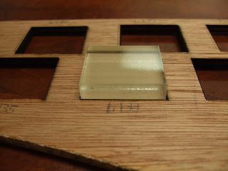
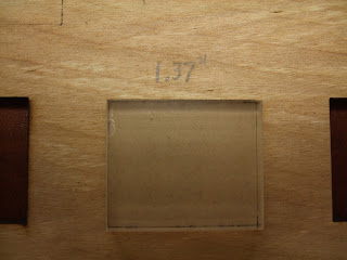
You can see from the picture that the 10 blocks at a first glance all look to have the same dimensions, and yet the lengths are decreasing by 0.01 inches going from left to right as marked numerically in the photograph.  Several zoomed in pictures show how the block falls through cleanly in several of the larger blocks on the left side, but only partially fall through or sit unevenly in a block which is too small to accommodate it.  It was in this manner that I was able to narrow down to a range of losses of material due to the burn and char debris.

Left mouse click on any image to enlarge it in a new window


Note there is some wiggle room around this inserted block


this one a bit less


this does not truly insert


side view


Now the vertical (shorter in this case) length is varied


decreasing to 1.13 inches prevents a true insertion


at 1.12 inches it is obviously not going to insert at all


Wednesday, January 24, 2018

Precision Cutting


Today I started a series of tests to see if a quantitative relationship could be developed to understand how a nominal dimension cut size in software translates into actual dimensions in flat wood. In other words, how much material is lost due to burn and charred dust that makes the cut dimension LONGER than the size indicated in the software design. I found that for a 1 inch block, the gap inbetween the cut-out block and the frame cut around it is about 1/32 inch. Knowing that the laser cut performance varies in the vertical and horizontal directions, I designed a series of 5 blocks for each dimension. The dimension being varied changes by 0.01 inch incrementally (1.39 , 1.38, 1.37, 1.36, 1.35 inches) for a nominal 1.4 inch horizontal. The verticals are varied also by 0.01 inches starting at 1.14 inch to 1.10 inch for a nominal 1.15 inch design dimension.

First, I tested various combinations of power and speed to see whether (a) the cut makes it through wood 3/16 inch thick, and (2) how much char burn dust is created along the cut edges.

This is a Boss Laser LS-2436 150 Watts and 4 inch focal length.

#1 35% power and 25mm/sec speed cut
#2 30% and 25 mm/sec no cut
#3 25% and 25 mm/sec no cut
#4 20% and 15 mm/sec cut
#5 15% and 15 mm/sec cut
#6 12% and 15 mm/sec no cut
#7 12% and 10 mm/sec no cut
#8 12% and 5  mm/sec cut

I assessed which combination of speed and power processes cuts with the least char debris by visually inspecting the sides and wiping all four edges of each cut-out block against the cotton terry cloth pictured below.

Wiping char dust on cloth to find the cleanest cut


To my eyes the 15 mm/sec and 15% power produced the best results.

So, when I set my parameters to 15/15 and ran my series of 10 test blocks, I was surprised to see that none of them had full cut-throughs! As you can see from the photos though, burn lines are evident to different extents on the backside of the wood, suggesting that the power only needs to be increased a bit to achieve full cut-throughs.


Front and back sides of a series of unsuccessful cut-throughs on 3/16 inch wood


Front


Back


What could possibly explain this? Two things that I can think of:

1. There is warping/unevenness in the wood and the metal bricks holding the wood in place are successful to different extents in keeping the wood perfectly flat.  Differences in flatness will affect the ability of the auto focus to work properly and thus affect the cutting strength. I will try to use more bricks to keep the wood flatter.

2. I made a mistake and did not match the laser frequency in the g-code files between the single (125 kHz) and multi-block designs (20 kHz). So I went back and resaved the multiblock deign with a 125 kHz setting and will cut the test series again.

To be continued ...

Monday, January 22, 2018

Cleaning the Plexiglass

I found that using a standard normal size wooden toothpick is a very good way to remove caked on plume haze off the plexiglass. You need to swap out toothpicks frequently, but you get very close to the artwork in tight spaces without ruining it. I also used wire clippers to cut fresh tips on the toothpicks and that can extend the toothpick if you are in short supply. Look at my before/after pictures attached. This was for the single scan of the rosebud.


Before using a toothpick


After cleaning for about 5 minutes with a toothpick


Wednesday, January 17, 2018

Yesterday I used the 4 inch focal length laser to scan a small inch square rosebud image. The image was cropped out of a larger botanical drawing by my mother using colored pencils.


Grayscale modified rosebud


single and triple scanned rosebuds in cast plexiglass


edge view of the single scanned rosebud


edge view of the triple scanned rosebud - a deeper etch.


Number of scans

One etch was scanned once and another one was scanned 3 times. The difference in depth is quite noticeable, as the 3 times etched design is much more three dimensional, although it was also harder to clean debris from it. Debris was cleaned by compressed canned air while the material was in the chamber and by a wet stiff toothbrush in a sink afterwards. I observed that compressed canned air was more effective at loosening and blowing away debris from the crevices of a 3 by 5 inch etch from last week than yesteray's 1 inch square etch.

Bed positioning

I experimented with mounting the cast plexiglass both towards the center, and also on the far right edge of the support bed, to the right of the ventilation holes. I found that considerably less plume debris was deposited on the untreated plexiglass surfaces if the material was more towards the center. I also observed that cut throughs induced orange flames were much longer when the material was to the right of the ventilation holes. I failed to take photos of the flame, and central bed position. The flames were often as long as my index finger without proper ventilation. The pictures will show you the differences on the plume debris deposited on the surface areas.

Plexiglass positioned away from reach of ventilation holes underneath the support bed


Laser head range

The farthest that the laser head can move back is slightly off the edge of the bed so that the positioning red light is no longer visible.  Whether it's acceptable to run the head to its extreme position can be discussed in the lab with co-workers.  It also appears that if you have the laser head moved into position far away from the previous origin, pressing the red ESC (escape) on the laser control pad appears to bring the laser and back to the previous working origin and halts there, but without actually running the file. This behavior of the escape key is not documented in the Operator's manual.

Laser head in resting position


Changing speed/power on the fly

If all you want to do is change the scan speed and power setting of a g-code file already loaded into memory, you do not need to return to your computer and regenerate that g-code file. On the main control screen of the laser, press Enter twice. Then presss the Z/U key to move up and down the editable speed and power fields. Once one is chosen as highlighted in blue, press the left arrow key to underline the numerical value you want to change. Then press the up and down keys of the laser keypad to cycle through the numbers zero to 9. After editing any field, press enter to save it. Press Enter again when done to return to the main menu. A feature of the on-board software is that after editing those parameters, the image on the view screen of your object goes blank. Fix this by pressing the File keypad button, reselect your g-code file from the list, press enter again, and the image thumbnail is again viewable. NOTE THAT THE NEW PARAMETERS ARE STILL IN PLACE; YOU HAVE NOT RELOADED THE ORIGINAL FILE. You simply have woken up the image to become viewable again.

direction matters

When cutting through the plexiglass to get the actual art piece to drop out loose, I noticed that the smoothness and minimization of ridges was far better in the horizontal direction than the vertical direction. I guessed incorrectly that increasing the speed from 15 to 30 mm/sec might improve the overall smoothness of the edges at 70% power. However, doing so failed to cut through the 3/8 inch plexiglass. Since I did not want to increase power further, I reverted back to 15 mm/sec to get a proper cut-through and will accept the smoothness quality as is for now.

Chamber coordinate system

While the scan is running, I observed the X coordinate, Y coordinate and Z coordinate values flashing quickly on the viewscreen. X values increase left to right. Y values increase top to bottom. Z values are steady of course, as neither the bed nor the laser head moves vertically while firing. The Z values were always positive. I therefore surmise that the Cartesian coordinate system of the laser chamber is left-handed.

time efficiency

The software controlling the horizontal gimble of the laser head has been well engineered from a time usage point of view. The X coordinates routinely adjusted based on the number of times the laser would need to fire to etch. In a horizontal row where very few pixels need to be etched the laser head skipped moving through the blank areas left and right of the etchable pixels, saving time.

Laser etching the rosebud into the plexiglass

low powers

You can edit power levels down to as low as 0.1% on-board the laser, but numbers 0.9% or lower are rounded up to 1.0%. A large number such as 70%, if edited to for example, 70.4%, will be respected as such in the main menu. Setting values to 1% is good trick to get a layer to go unfired, instead of needing to create and load a new file from scratch. This only makes sense though if the layer has a short run time.